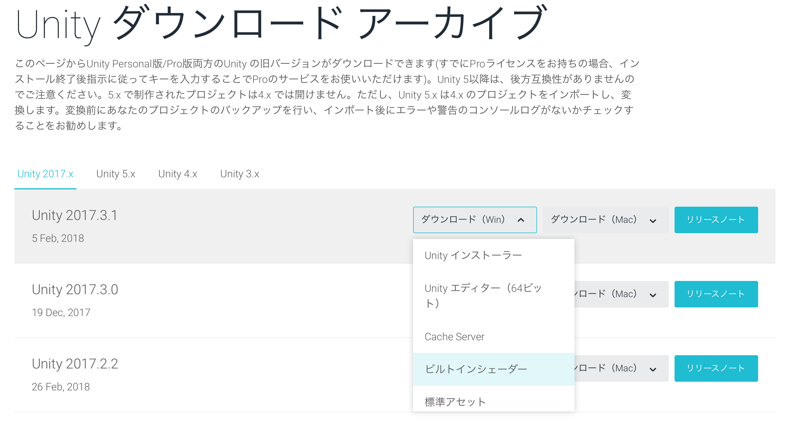
Figure 4.1: https://unity3d.com/jp/get-unity/download/archive
Hello! It's Sugihiro Nori! I'm sorry I couldn't write an article in the previous "UnityGraphicsPrograming Vol1"! Thanks to Oishi-kun for writing on behalf of me (._.)
Here, I would like to explain the spray program that I could not write last time. The code of Unity is a little better than the one at the time of Vol1!
First, let's implement a simple lighting effect by ourselves without using Unity's Built-in lights. Then, as an application, I will explain the development of the process of painting 3D objects with a spray. The concept of this chapter is to follow the flow of creating your own functions by referring to UnityCG.cginc and built-in processing and applying them to new functions. I think.
The samples in this chapter are in the ProjectionSpray folder at
https://github.com/IndieVisualLab/UnityGraphicsProgramming2 .
Light in Unity is extremely useful. Just install a light object and the world will be brighter. When you select a shadow from the Inspector, a shadow map is automatically created and the shadow is cast from the object.
First of all, we will implement the light independently while watching how Unity implements the light.
In Unity, you can download the material shaders included by default and the internally used CGINC files from the Unity Download Archive.
It will be helpful when writing your own shader, and you can learn more about CG depiction, so I recommend you to download and see it!
Figure 4.1: https://unity3d.com/jp/get-unity/download/archive
The writing-related files that may be relevant in this chapter are:
Let's take a look at the basic Lambert Lighting. ( Listing 4.1 ) Mr. Lambert thought.
Listing 4.1: Lighting.cginc
 1: struct SurfaceOutput {
 2:     fixed3 Albedo;
 3:     fixed3 Normal;
 4:     fixed3 Emission;
 5:     half Specular;
 6:     fixed Gloss;
 7:     fixed Alpha;
 8: };
 9: ~~
10: inline fixed4 UnityLambertLight (SurfaceOutput s, UnityLight light)
11: {
12:     fixed diff = max (0, dot (s.Normal, light.dir));
13:
14:     fixed4 c;
15:     c.rgb = s.Albedo * light.color * diff;
16:     c.a = s.Alpha;
17:     return c;
18: }
In the actual lighting calculation, the diffuse value is calculated from the inner product of the direction from the light to the mesh and the normal direction of the mesh. Listing 4.1
fixed diff = max (0, dot (s.Normal, light.dir));
For Unity Lights that are undefined in Lighting.cginc, they are defined in UnityLightingCommon.cginc and contain information about the color and direction of the lights. Listing 4.2
Listing 4.2: UnityLightingCommon.cginc
 1: struct UnityLight
 2: {
 3:     half3 color;
 4: half3 you;
 5:
 6:     // Deprecated: Ndotl is now calculated on the fly
 7:     // and is no longer stored. Do not used it.
 8:     half  ndotl;
 9: };
Looking at the actual lighting process, I found that the calculation of lighting requires mesh normal information, so let's take a quick look at how to display mesh normal information in Shader. ..
See the scene in 00_viewNormal.unity in the sample project .
The object has a material that outputs normal information as a color, and its shader is shown in Listing 4.3 .
Listing 4.3: simple-showNormal.shader
 1: struct appdata
 2: {
 3:     float4 vertex : POSITION;
 4: float3 normal: NORMAL;
 5: };
 6:
 7: struct v2f
 8: {
 9:     float3 worldPos : TEXCOORD0;
10:     float3 normal : TEXCOORD1;
11:     float4 vertex : SV_POSITION;
12: };
13:
14: v2f vert (appdata v)
15: {
16:     v2f o;
17:     o.vertex = UnityObjectToClipPos(v.vertex);
18:     o.normal = UnityObjectToWorldNormal(v.normal);
19:     return o;
20: }
21:
22: half4 frag (v2f i) : SV_Target
23: {
24:     fixed4 col = half4(i.normal,1);
25:     return col;
26: }
The vertex shader (v2f vert) calculates the normal direction of the mesh in the world coordinate system and passes it to the fragment shader (half4 frag). In the fragment shader, the passed normal information is converted to color with the x component as R, the y component as G, and the z component as B, and output as it is. Listing 4.3
Even if the part looks black on the image, the normal x may actually have a negative value. Figure 4.2
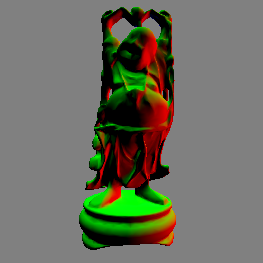
図4.2: 00_viewNormal.unity
The mesh is now ready for lighting.
There is a built-in utility function in UnityCG.cginc that makes it easy to write shaders. For example, the vertex position used in Listing 4.3UnityObjectToClipPos transforms from the object (local) coordinate system to the clip coordinate system. Also, UnityObjectToWorldNormalthe function of is converting the normal direction from the object coordinate system to the world coordinate system.
For other functions, please refer to UnityCG.cginc or the official manual as it is convenient for writing shaders. https://docs.unity3d.com/ja/current/Manual/SL-BuiltinFunctions.html
Also, if you want to know more about coordinate transformation and each coordinate system, you may be able to learn more by referring to Unity Graphics Programming vol.1 and Mr. Fukunaga's "Chapter 9 Multi Plane Perspective Projection".
See the scene at 01_pointLight.unity in the sample project .
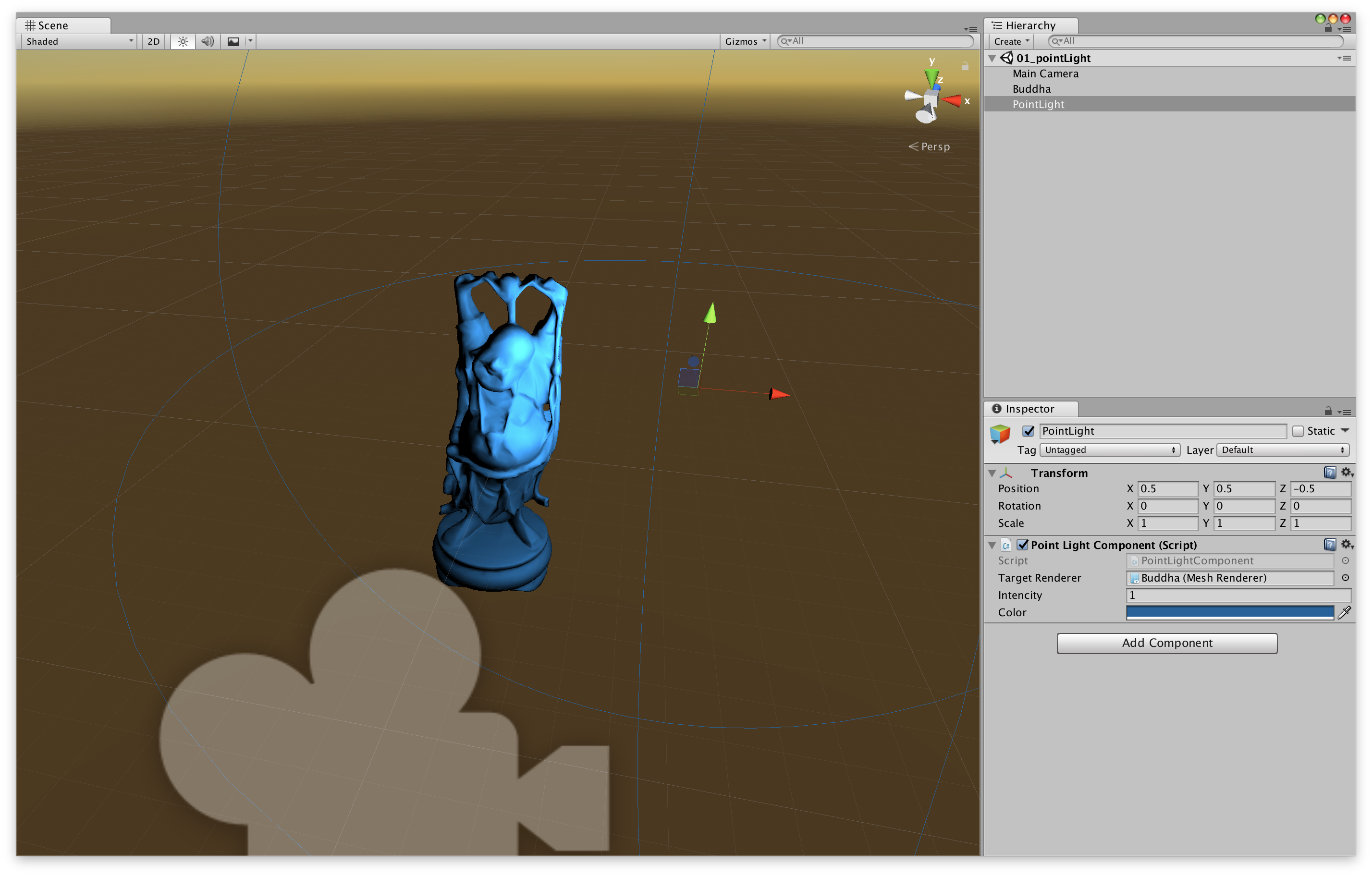
図4.3: 01_pointLight.unity
A point light source is a light source that illuminates all directions from a certain point. The scene has a Buddha mesh object and a PointLight object. The PointLight object has a script ( Listing 4.4 ) for sending light information to the mesh, and based on that light information, the lighting result is displayed as a material ( Listing 4.5 ).
Listing 4.4: PointLightComponent.cs
 1: using UnityEngine;
 2:
 3: [ExecuteInEditMode]
 4: public class PointLightComponent : MonoBehaviour
 5: {
 6:     static MaterialPropertyBlock mpb;
 7:
 8:     public Renderer targetRenderer;
 9:     public float intensity = 1f;
10:     public Color color = Color.white;
11:
12:     void Update()
13:     {
14:         if (targetRenderer == null)
15:             return;
16:         if (mpb == null)
17:             mpb = new MaterialPropertyBlock();
18:
19:         targetRenderer.GetPropertyBlock(mpb);
20:         mpb.SetVector("_LitPos", transform.position);
21:         mpb.SetFloat("_Intensity", intensity);
22:         mpb.SetColor("_LitCol", color);
23:         targetRenderer.SetPropertyBlock(mpb);
24:     }
25:
26:     private void OnDrawGizmos()
27:     {
28:         Gizmos.color = color;
29:         Gizmos.DrawWireSphere(transform.position, intensity);
30:     }
31: }
This component passes the position, intensity and color of the light to the target mesh. And, the material to perform the writing process is set based on the received information.
Values are set from CSharp for each property of "_LitPos", "_LitCol"and "_Intensity"of the material .
Listing 4.5: simple-pointLight.shader
 1: Shader "Unlit/Simple/PointLight-Reciever"
 2: {
 3:     Properties
 4:     {
 5:         _LitPos("light position", Vector) = (0,0,0,0)
 6:         _LitCol("light color", Color) = (1,1,1,1)
 7:         _Intensity("light intensity", Float) = 1
 8:     }
 9:     SubShader
10:     {
11:         Tags { "RenderType"="Opaque" }
12: LOD 100
13:
14:         Pass
15:         {
16:             CGPROGRAM
17:             #pragma vertex vert
18:             #pragma fragment frag
19:
20:             #include "UnityCG.cginc"
21:
22:             struct appdata
23:             {
24:                 float4 vertex : POSITION;
25: float3 normal: NORMAL;
26:             };
27:
28:             struct v2f
29:             {
30:                 float3 worldPos : TEXCOORD0;
31:                 float3 normal : TEXCOORD1;
32:                 float4 vertex : SV_POSITION;
33:             };
34:
35:             half4 _LitPos, _LitCol;
36:             half _Intensity;
37:
38:             v2f vert (appdata v)
39:             {
40:                 v2f o;
41:                 o.vertex = UnityObjectToClipPos(v.vertex);
42:                 o.worldPos = mul(unity_ObjectToWorld, v.vertex).xyz;
43: // Pass the position of the mesh in the world coordinate system to the fragment shader
44:                 o.normal = UnityObjectToWorldNormal(v.normal);
45:                 return o;
46:             }
47:
48:             fixed4 frag (v2f i) : SV_Target
49:             {
50:                 half3 to = i.worldPos - _LitPos;
51: // Vector from light position to mesh position
52:                 half3 lightDir = normalize(to);
53:                 half dist = length(to);
54:                 half atten =
55:                     _Intensity * dot(-lightDir, i.normal) / (dist * dist);
56:
57:                 half4 col = max(0.0, atten) * _LitCol;
58:                 return col;
59:             }
60:             ENDCG
61:         }
62:     }
63: }
The lighting calculation is based on the basic Lambert Lighting ( Listing 4.1 ) calculation, and the intensity is attenuated in inverse proportion to the square of the distance. Listing 4.5
half atten = _Intensity * dot(-lightDir, i.normal) / (dist * dist);
It's a simple system of one light for one model, but I was able to implement the lighting process.
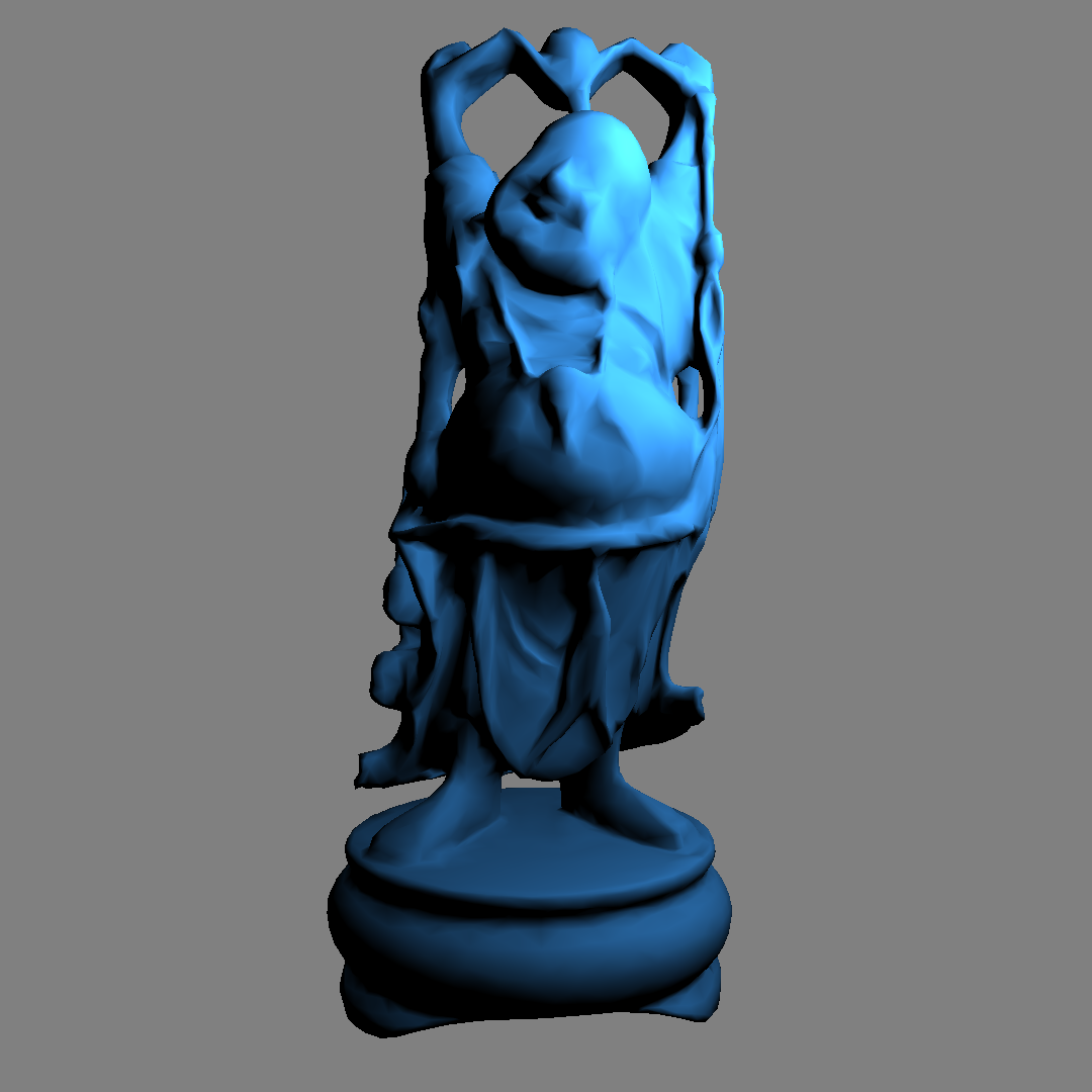
図4.4: 01_pointLight.unity
Next, let's implement the spotlight. Unlike point lights, spotlights are directional lights that emit light in one direction.
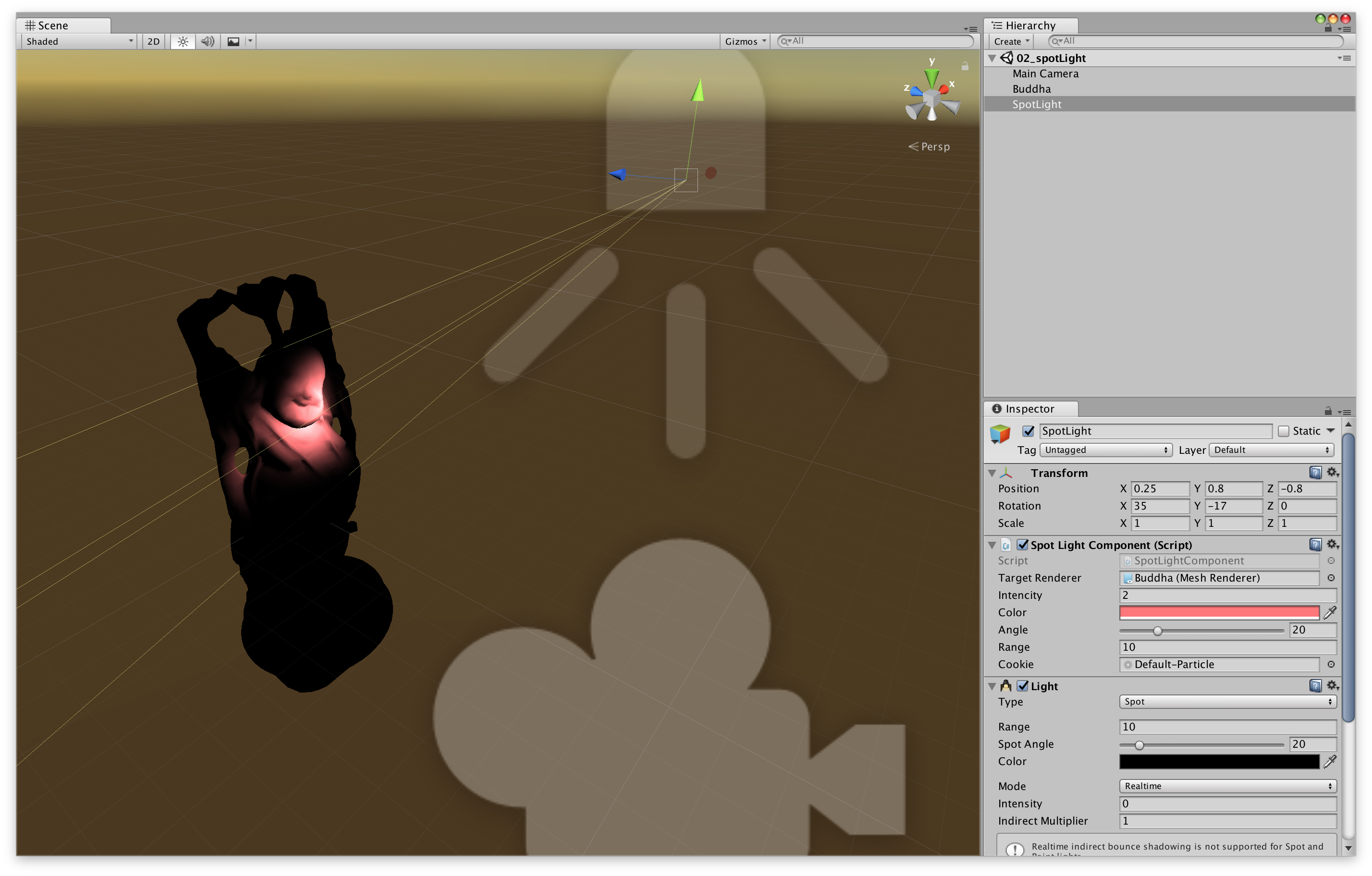
図4.5: 02_spotLight.unity
We are using standard Unity lights here just for the Gizmo display of the spotlights. Figure 4.5
Since the spotlight is directional, the direction of the light and the spot angle (angle) information will be added to the point light in addition to the position information. This information is of light worldToLightMatrix, projectionMatrixrespectively, as Matrix4x4(that's Shader float4x4Passes in the properties of).
In addition, the spotlight can also set a Light Cookie. (Unity has a default LightCookie, but I couldn't select it from the editor, so I'm using the Default-Particle texture)
Listing 4.6: SpotLightComponent.cs
 1: using UnityEngine;
 2:
 3: [ExecuteInEditMode]
 4: public class SpotLightComponent : MonoBehaviour
 5: {
 6:     static MaterialPropertyBlock mpb;
 7:
 8:     public Renderer targetRenderer;
 9:     public float intensity = 1f;
10:     public Color color = Color.white;
11:     [Range(0.01f, 90f)] public float angle = 30f;
12:     public float range = 10f;
13:     public Texture cookie;
14:
15:     void Update()
16:     {
17:         if (targetRenderer == null)
18:             return;
19:         if (mpb == null)
20:             mpb = new MaterialPropertyBlock();
21:
22: // Calculating projectionMatrix
23:         var projMatrix = Matrix4x4.Perspective(angle, 1f, 0f, range);
24:         var worldToLightMatrix = transform.worldToLocalMatrix;
25:
26:         targetRenderer.GetPropertyBlock(mpb);
27:         mpb.SetVector("_LitPos", transform.position);
28:         mpb.SetFloat("_Intensity", intensity);
29:         mpb.SetColor("_LitCol", color);
30:         mpb.SetMatrix("_WorldToLitMatrix", worldToLightMatrix);
31:         mpb.SetMatrix("_ProjMatrix", projMatrix);
32:         mpb.SetTexture("_Cookie", cookie);
33:         targetRenderer.SetPropertyBlock(mpb);
34:     }
35: }
projectionMatrix is Matrix4x4.Perspective(angle, 1f, 0f, range)calculated by.
Shader calculates and displays the lighting process based on the parameter information received from the spotlight. Listing 4.7
Listing 4.7: simple-spotLight.shader
 1: uniform float4x4 _ProjMatrix, _WorldToLitMatrix;
 2:
 3: sampler2D _Cookie;
 4: half4 _LitPos, _LitCol;
 5: half _Intensity;
 6:
 7: ~~
 8:
 9: fixed4 frag (v2f i) : SV_Target
10: {
11:     half3 to = i.worldPos - _LitPos.xyz;
12:     half3 lightDir = normalize(to);
13:     half dist = length(to);
14:     half atten = _Intensity * dot(-lightDir, i.normal) / (dist * dist);
15:
16:     half4 lightSpacePos = mul(_WorldToLitMatrix, half4(i.worldPos, 1.0));
17:     half4 projPos = mul(_ProjMatrix, lightSpacePos);
18: projPos.z * = -1;
19: half2 litUv = projPos.xy / projPos.z;
20: litUv = litUv * 0.5 + 0.5;
21:     half lightCookie = tex2D(_Cookie, litUv);
22:     lightCookie *=
23:         0<litUv.x && litUv.x<1 && 0<litUv.y && litUv.y<1 && 0<projPos.z;
24:
25:     half4 col = max(0.0, atten) * _LitCol * lightCookie;
26:     return col;
27: }
28:
You can see that it's basically the same as a point light except for the fragment shader. Listing 4.7
From the 16th line to the 22nd line, the intensity at each point of the spotlight is calculated. When viewed from the position of the light, the light cookie at that point is sampled to determine whether the point is within the range of the light and the intensity of the light.
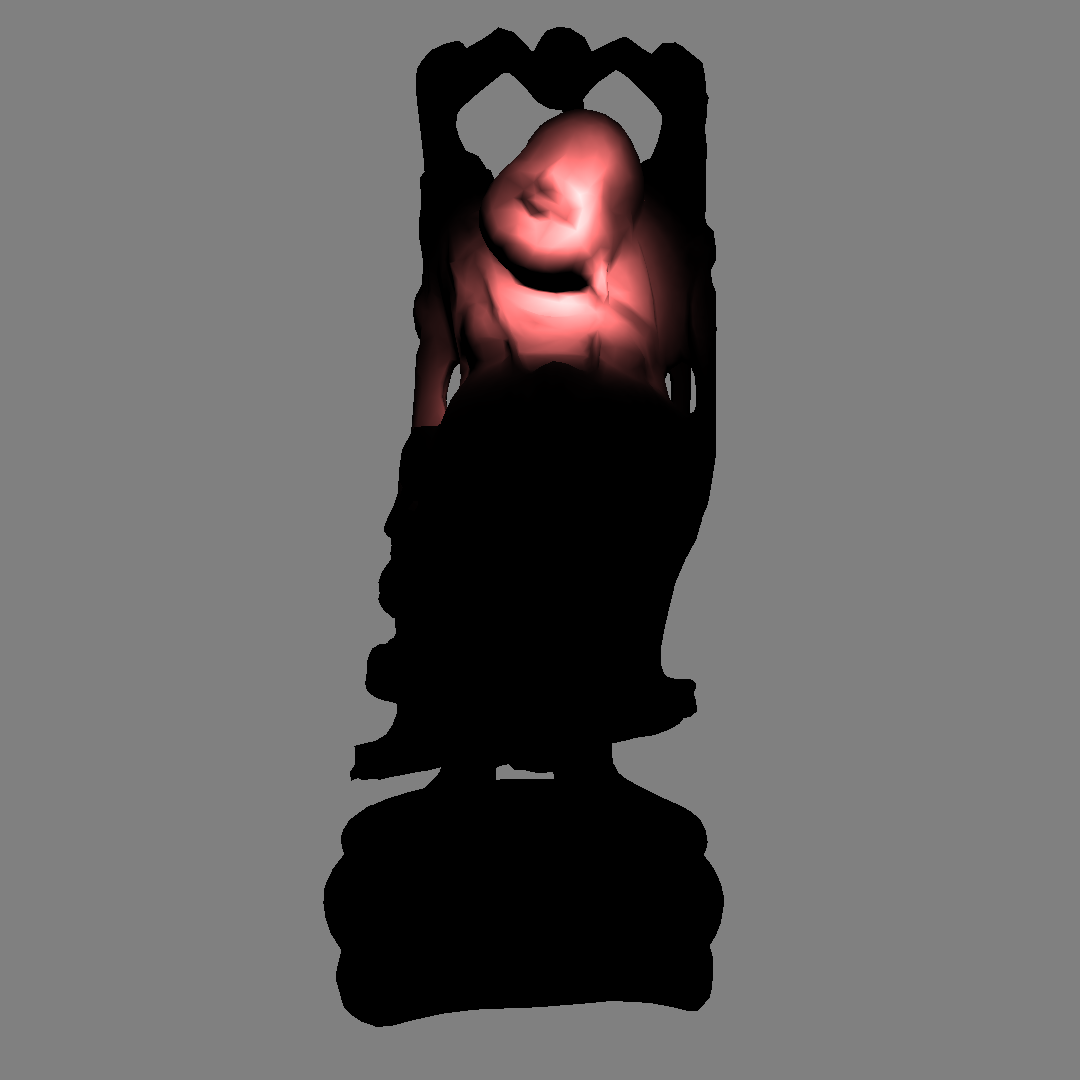
図4.6: 02_spotLight.unity
For the spotlight cookie processing, UnitySpotCookie()the part in the built-in CGINC, AutoLight.cginc will be helpful.
Listing 4.8: AutoLight.cginc
 1: #ifdef SPOT
 2: sampler2D _LightTexture0;
 3: unityShadowCoord4x4 unity_WorldToLight;
 4: sampler2D _LightTextureB0;
 5: inline fixed UnitySpotCookie(unityShadowCoord4 LightCoord)
 6: {
 7:     return tex2D(
 8:         _LightTexture0,
 9:         LightCoord.xy / LightCoord.w + 0.5
10:     ).w;
11: }
12: inline fixed UnitySpotAttenuate(unityShadowCoord3 LightCoord)
13: {
14:     return tex2D(
15:         _LightTextureB0,
16:         dot(LightCoord, LightCoord).xx
17:     ).UNITY_ATTEN_CHANNEL;
18: }
19: #define UNITY_LIGHT_ATTENUATION(destName, input, worldPos) \
20:     unityShadowCoord4 lightCoord = mul( \
21:         unity_WorldToLight, \
22:         unityShadowCoord4(worldPos, 1) \
23:     ); \
24:     fixed shadow = UNITY_SHADOW_ATTENUATION(input, worldPos); \
25:     fixed destName = \
26:         (lightCoord.z > 0) * \
27:         UnitySpotCookie(lightCoord) * \
28:         UnitySpotAttenuate(lightCoord.xyz) * shadow;
29: #endif
Finally, as a lighting implementation, let's implement a shadow.
Light comes out of the light, the mesh that is directly exposed to light becomes brighter, there is something else between the light and the mesh, and the mesh that is blocked by light becomes darker. This is the shadow.
As a procedure, roughly
It will be in the form of. This time we need a depth texture from the position of the light, so we'll add a Camera component to SpotLight to create the depth texture as seen from the light.
図4.7: 03_spotLight-withShadow.unity
Camera (built-in) is attached to SpotLightComponent (self-made). Figure 4.7
Listing 4.9: SpotLightWithShadow.cs
 1: Shader depthRenderShader {
 2:     get { return Shader.Find("Unlit/depthRender"); }
 3: }
 4:
 5: new Camera camera
 6: {
 7:     get
 8:     {
 9:         if (_c == null)
10:         {
11:             _c = GetComponent<Camera>();
12:             if (_c == null)
13:                 _c = gameObject.AddComponent<Camera>();
14:             depthOutput = new RenderTexture(
15:                 shadowMapResolution,
16:                 shadowMapResolution,
17:                 16,
18:                 RenderTextureFormat.RFloat
19:             );
20:             depthOutput.wrapMode = TextureWrapMode.Clamp;
21:             depthOutput.Create();
22:             _c.targetTexture = depthOutput;
23:             _c.SetReplacementShader(depthRenderShader, "RenderType");
24:             _c.clearFlags = CameraClearFlags.Nothing;
25:             _c.nearClipPlane = 0.01f;
26:             _c.enabled = false;
27:         }
28:         return _c;
29:     }
30: }
31: Room _c;
32: RenderTexture depthOutput;
33:
34: void Update()
35: {
36:     if (mpb == null)
37:         mpb = new MaterialPropertyBlock();
38:
39:     var currentRt = RenderTexture.active;
40:     RenderTexture.active = depthOutput;
41:     GL.Clear(true, true, Color.white * camera.farClipPlane);
42:     camera.fieldOfView = angle;
43:     camera.nearClipPlane = 0.01f;
44:     camera.farClipPlane = range;
45:     camera.Render();
46: // Camera rendering is done manually in the script
47:     RenderTexture.active = currentRt;
48:
49:     var projMatrix = camera.projectionMatrix;
50: // Use the camera's projection matrix
51:     var worldToLightMatrix = transform.worldToLocalMatrix;
52:
53:     ~~
54: }
The C # script is almost the same as the shadowless version, but with the camera set to render the depth texture and the ReplacementShader to render the depth. Also, since we have a camera this time Matrix4x4.Perspective, Camera.projectionMatrixwe will use the projection matrix instead of .
The shader for depth texture generation looks like this:
Listing 4.10: depthRender.shader
 1:     v2f vert (float4 pos : POSITION)
 2:     {
 3:         v2f o;
 4:         o.vertex = UnityObjectToClipPos(pos);
 5:         o.depth = abs(UnityObjectToViewPos(pos).z);
 6:         return o;
 7:     }
 8:
 9:     float frag (v2f i) : SV_Target
10:     {
11:         return i.depth;
12:     }
The generated depth texture ( Fig. 4.8 ) outputs the z-coordinate value of the position of the object in the light coordinate system (camera coordinate system).
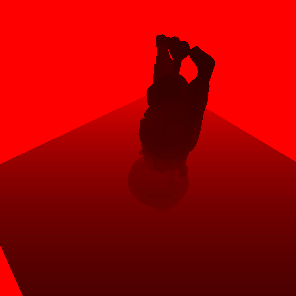
図4.8: light depthTexture
depthOutputPass the generated depth texture ( ) to the mesh object and render the object. The calculated part of the shadow of the object looks like this:
Listing 4.11: simple-spotLight-withShadow.shader
 1: fixed4 frag (v2f i) : SV_Target
 2: {
 3:     ///diffuse lighting
 4:     half3 to = i.worldPos - _LitPos.xyz;
 5:     half3 lightDir = normalize(to);
 6:     half dist = length(to);
 7:     half atten = _Intensity * dot(-lightDir, i.normal) / (dist * dist);
 8:
 9:     ///spot-light cookie
10:     half4 lightSpacePos = mul(_WorldToLitMatrix, half4(i.worldPos, 1.0));
11:     half4 projPos = mul(_ProjMatrix, lightSpacePos);
12: projPos.z * = -1;
13: half2 litUv = projPos.xy / projPos.z;
14: litUv = litUv * 0.5 + 0.5;
15:     half lightCookie = tex2D(_Cookie, litUv);
16:     lightCookie *=
17:         0<litUv.x && litUv.x<1 && 0<litUv.y && litUv.y<1 && 0<projPos.z;
18:
19:     ///shadow
20:     half lightDepth = tex2D(_LitDepth, litUv).r;
21: // _LitDepth is passed the depth texture seen from the light
22:     atten *= 1.0 - saturate(10*abs(lightSpacePos.z) - 10*lightDepth);
23:
24:     half4 col = max(0.0, atten) * _LitCol * lightCookie;
25:     return col;
26: }
Made the depth texture by the camera tex2D(_LitTexture, litUv).rand lightSpacePos.zis, z value of the vertex position of both viewed from the light object is stored. Since the texture is _LitTexturethe information of the surface seen from the light = the surface exposed to the light, it is judged whether it is a shadow or not by comparing it with the value ( lightDepth) sampled from the depth texture lightSpacePos.z.
atten *= 1.0 - saturate(10*abs(lightSpacePos.z) - 10*lightDepth);
In the code here, the lightDepthhigher lightSpacePos.zthe value, the darker the surface.
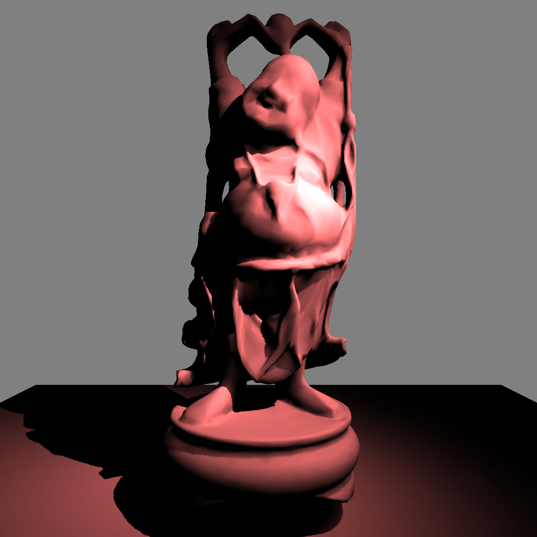
図4.9: 03_spotLight-withShadow.unity
You can now see the shadow of the object in the spotlight.
Using this spotlight and shadow implementation, we will implement a spray function that colors objects in real time.
Unity scene: in Example, compareMatrix.unity
Listing 4.12: CompareMatrix.cs
 1:     float fov = 30f;
 2:     float near = 0.01f;
 3:     float far = 1000f;
 4:
 5:     camera.fieldOfView = fov;
 6:     camera.nearClipPlane = near;
 7:     camera.farClipPlane = far;
 8:
 9:     Matrix4x4 cameraMatrix = camera.projectionMatrix;
10:     Matrix4x4 perseMatrix = Matrix4x4.Perspective(
11:         fov,
12:         1f,
13:         near,
14:         far
15:     );
From here, we will apply our own SpotLightComponent to implement the spray function that allows you to paint objects.
Basically, it draws on the texture of the object based on the value of the lighting intensity. Since the Buddha object used this time does not have uv data, it is not possible to paste the texture as it is, but Unity has a function to generate UV for LightMap.
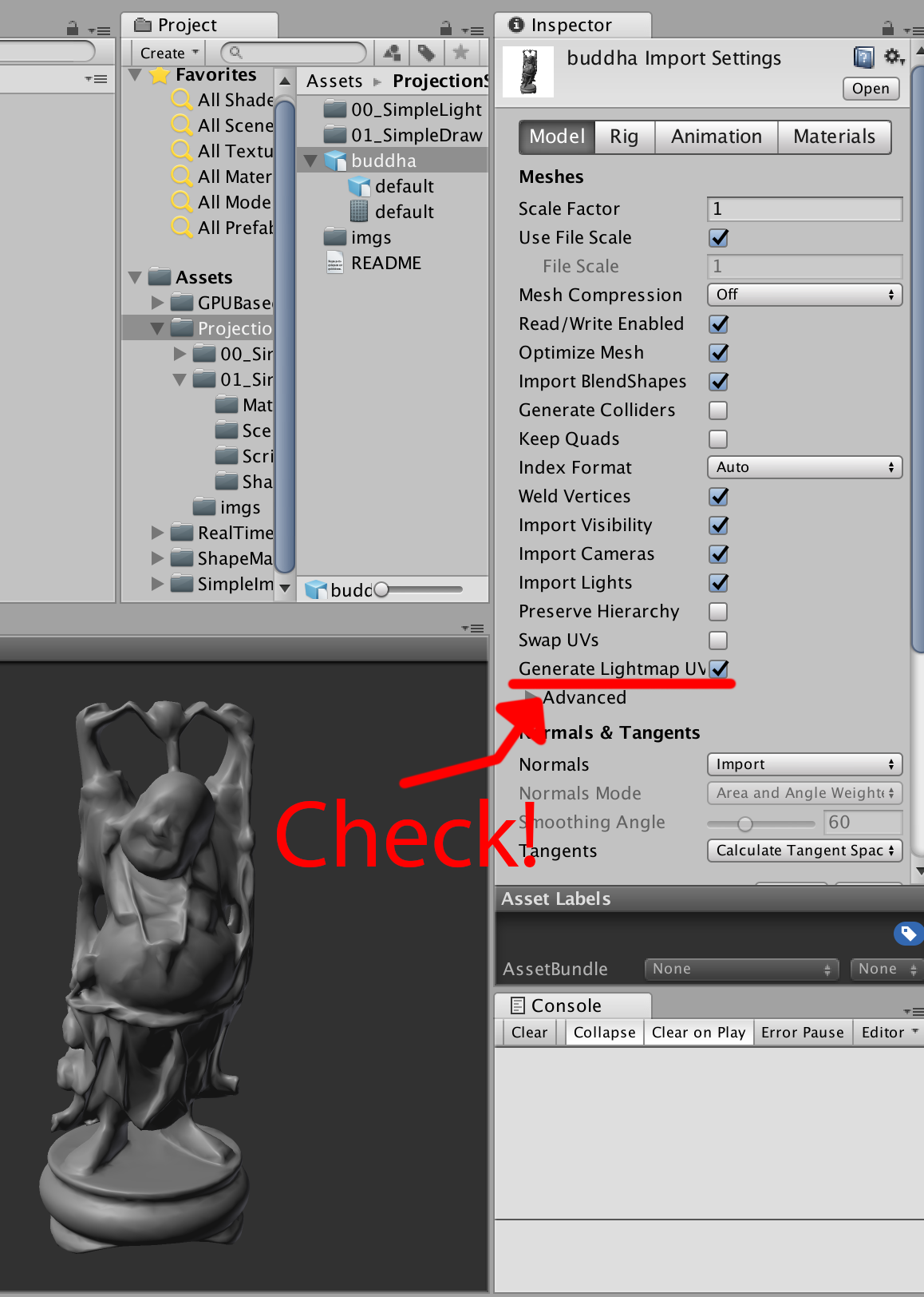
図4.10: buddha Import Setting
If you check the "Generate Lightmap UVs" item in the model Import Setting, UVs for the lightmap will be generated. ( v.uv2 : TEXCOORD1) Create a drawable RenderTexture for this Uv2 and draw it.
See 00_showUv2.unity for a sample scene .
In order to write to the texture that maps to mesh.uv2, we need to generate a texture that is expanded from the mesh to UV2. First, let's create a shader that expands the vertices of the mesh to the coordinates of UV2.
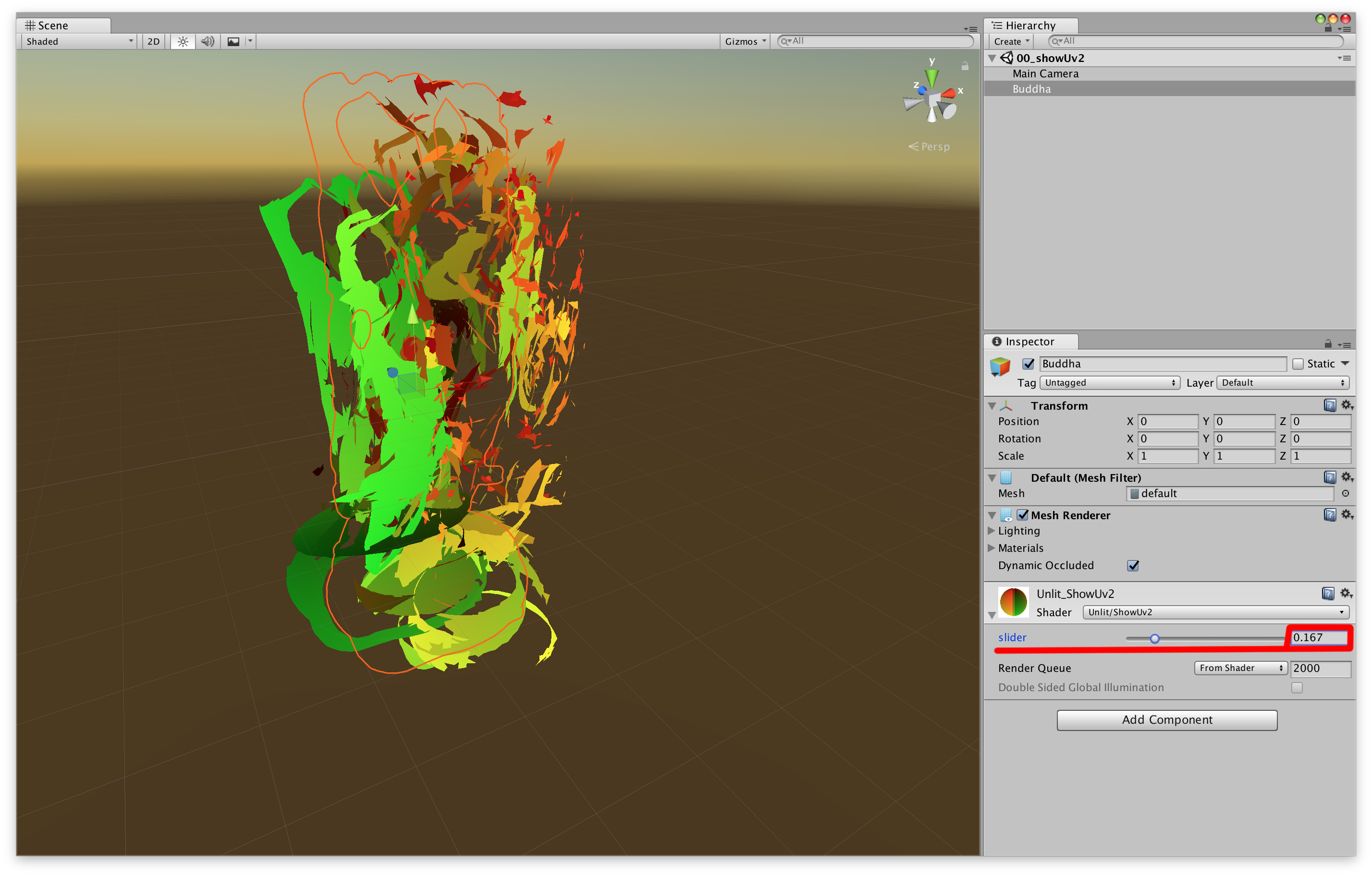
Figure 4.11: 00_showUv2.unity
Selecting a Buddha object in the scene and manipulating the material's "slider" parameter will change the object from its original shape to its Uv2 expanded shape. Coloring is, uv2.xywo color.rghas been assigned to.
Listing 4.13: showUv2.shader
 1: float _T;
 2:
 3: v2f vert(appdata v)
 4: {
 5: #if UNITY_UV_STARTS_AT_TOP
 6: v.uv2.y = 1.0 - v.uv2.y;
 7: #endif
 8:     float4 pos0 = UnityObjectToClipPos(v.vertex);
 9: float4 pos1 = float4 (v.uv2 * 2.0 - 1.0, 0.0, 1.0);
10:
11:     v2f o;
12:     o.vertex = lerp(pos0, pos1, _T);
13: o.uv2 = v.uv2;
14:     o.worldPos = mul(unity_ObjectToWorld, v.vertex).xyz;
15:     o.normal = UnityObjectToWorldNormal(v.normal);
16:     return o;
17: }
18:
19: half4 frag(v2f i) : SV_Target
20: {
21:     return half4(i.uv2,0,1);
22: }
float4 pos1 = float4(v.uv2*2.0 - 1.0, 0.0, 1.0);The value of is the position expanded to Uv2 in the clip coordinate system. Listing 4.13
Since we are passing the value of worldPosand to normalthe fragment shader, we will use this value to handle the lighting in the spotlight calculation.
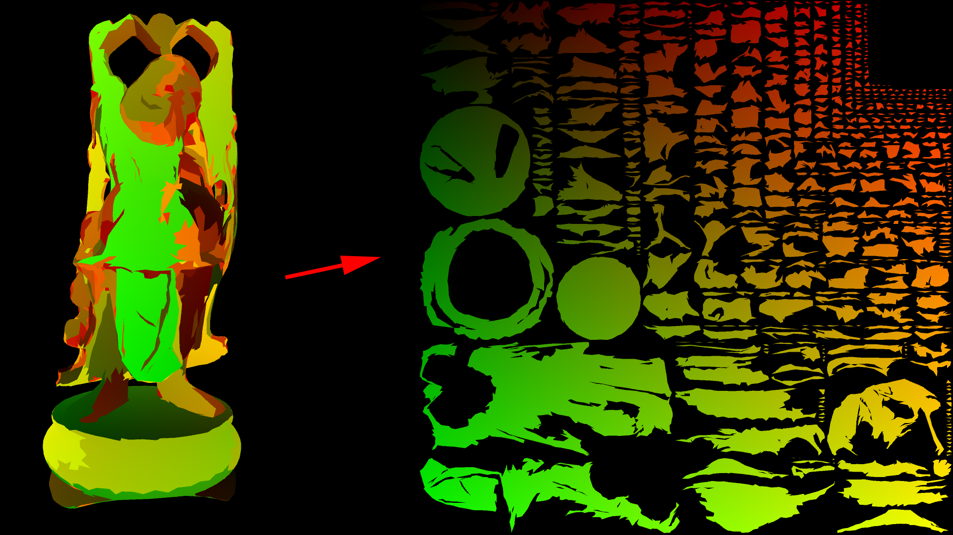
Figure 4.12: 00_showUv2.unity
You can generate textures expanded from mesh to Uv2!
Now that we're ready, we'll implement the spray functionality. See the scene at 01_projectionSpray.unity .
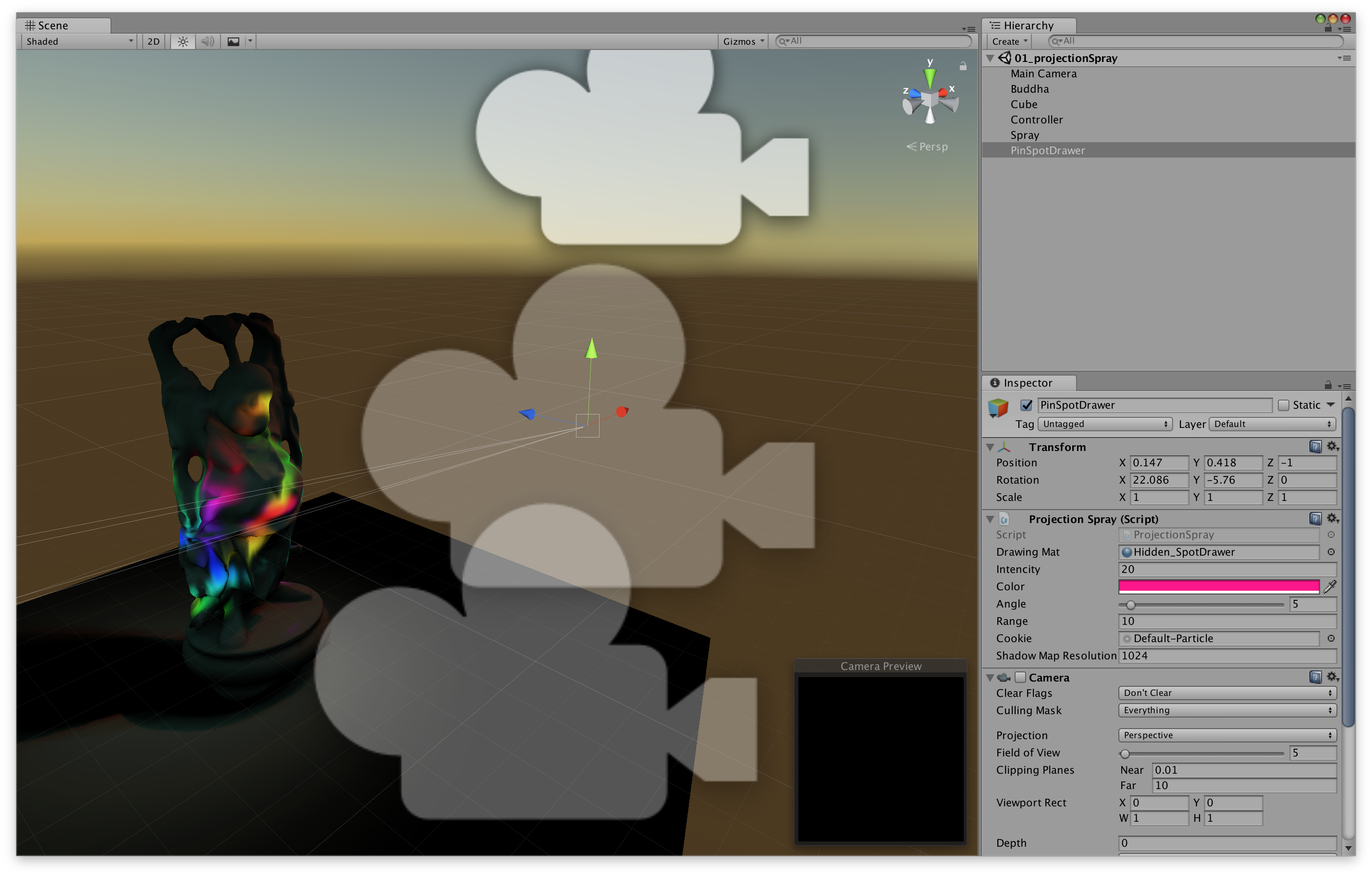
図4.13: 01_projectionSpray.unity
As you run this scene, the black Buddha objects will gradually become colored. Then, when you click on the screen, that part will be sprayed with a colorful color.
In terms of implementation content, it is an application of the self-made spotlight that has been implemented so far. The spotlight lighting calculation is not used for lighting RenderTextureas it is, but is used for updating. In this example, the texture you wrote is mapped to the one generated for the lightmap mesh.uv2.
DrawableIs a component attached to the object to be sprayed and is being drawn into the texture. ProjectionSprayThe component Materialsets properties for drawing on the texture, such as the position of the spray . As the processing flow , we call in DrawableControllerthe Updatefunction of projectionSpray.Draw(drawable)and draw on the texture.
Material drawMat: Material for drawingUpdateDrawingMat(): Update material settings before drawingDraw(Drawable drawable)Pass : drawMatto drawable.Draw(Material mat)and draw.Listing 4.14: projectionSpray.cs
 1: public class ProjectionSpray : MonoBehaviour {
 2:
 3:     public Material drawingMat;
 4:
 5:     public float intensity = 1f;
 6:     public Color color = Color.white;
 7:     [Range(0.01f, 90f)] public float angle = 30f;
 8:     public float range = 10f;
 9:     public Texture cookie;
10:     public int shadowMapResolution = 1024;
11:
12:     Shader depthRenderShader {
13:         get { return Shader.Find("Unlit/depthRender"); }
14:     }
15:
16:     new Camera camera{get{~~}}
17: Room _c;
18:     RenderTexture depthOutput;
19:
20:     public void UpdateDrawingMat()
21:     {
22:         var currentRt = RenderTexture.active;
23:         RenderTexture.active = depthOutput;
24:         GL.Clear(true, true, Color.white * camera.farClipPlane);
25:         camera.fieldOfView = angle;
26:         camera.nearClipPlane = 0.01f;
27:         camera.farClipPlane = range;
28:         camera.Render();
29: // Update depth texture
30:         RenderTexture.active = currentRt;
31:
32:         var projMatrix = camera.projectionMatrix;
33:         var worldToDrawerMatrix = transform.worldToLocalMatrix;
34:
35:         drawingMat.SetVector("_DrawerPos", transform.position);
36:         drawingMat.SetFloat("_Emission", intensity * Time.smoothDeltaTime);
37:         drawingMat.SetColor("_Color", color);
38:         drawingMat.SetMatrix("_WorldToDrawerMatrix", worldToDrawerMatrix);
39:         drawingMat.SetMatrix("_ProjMatrix", projMatrix);
40:         drawingMat.SetTexture("_Cookie", cookie);
41:         drawingMat.SetTexture("_DrawerDepth", depthOutput);
42: // The property name is different, but the information passed is the same as the spotlight.
43:     }
44:
45:     public void Draw(Drawable drawable)
46:     {
47:         drawable.Draw(drawingMat);
48: // The drawing process itself is done with Drawable.
49: // Projection Spray has the Material to draw.
50:     }
51: }
The object to be drawn by spraying. It has a texture for drawing. Start()In the function RenderTexturecreates a. It uses the classic Ping-pong Buffer.
Let's see the processing of the part that draws on the texture
Listing 4.15: Drawable.cs
1: // This function is called from projectionSpray.Draw (Drawable drawable)
2: public void Draw(Material drawingMat)
3: {
4: drawingMat.SetTexture("_MainTex", pingPongRts[0]);
5: // Set the current state of the texture to be drawn as the material.
6:
7: var currentActive = RenderTexture.active;
8: RenderTexture.active = pingPongRts[1];
9: // Set the texture to be drawn.
10: GL.Clear(true, true, Color.clear);
11: // Clear the texture to be drawn.
12: drawingMat.SetPass(0);
13: Graphics.DrawMeshNow(mesh, transform.localToWorldMatrix);
14: // Updated texture with target mesh and transform values to draw.
15: RenderTexture.active = currentActive;
16:
17: Swap(pingPongRts);
18:
19: if(fillCrack!=null)
20: {
21: // This is a process to prevent cracks from forming at the joints of Uv.
22: Graphics.Blit(pingPongRts[0], pingPongRts[1], fillCrack);
23: Swap(pingPongRts);
24: }
25:
26: Graphics.CopyTexture(pingPongRts[0], output);
27: // Copy the updated texture to output
28: }
The point here is that we are updating Graphics.DrawMeshNow(mesh, matrix)using RenderTexture. Since the vertex shader of ( Listing 4.15 ) expands drawingMatthe vertices of mesh.uv2the mesh into the shape of, it is possible to update the texture after passing the vertex position, normal, and transform information of the mesh to the fragment shader. .. ( Listing 4.16 )
Listing 4.16: ProjectionSpray.shader
 1: v2f vert (appdata v)
 2: {
 3: v.uv2.y = 1.0 - v.uv2.y;
 4: // Invert and!
 5:
 6:     v2f o;
 7:     o.vertex = float4(v.uv2*2.0 - 1.0, 0.0, 1.0);
 8: // Same process as showUv2!
 9:     o.uv = v.uv2;
10:     o.worldPos = mul(unity_ObjectToWorld, v.vertex).xyz;
11:     o.normal = UnityObjectToWorldNormal(v.normal);
12:     return o;
13: }
14:
15: sampler2D _MainTex;
16:
17: uniform float4x4 _ProjMatrix, _WorldToDrawerMatrix;
18:
19: sampler2D _Cookie, _DrawerDepth;
20: half4 _DrawerPos, _Color;
21: half _Emission;
22:
23: half4 frag (v2f i) : SV_Target
24: {
25:     ///diffuse
26:     half3 to = i.worldPos - _DrawerPos.xyz;
27:     half3 dir = normalize(to);
28:     half dist = length(to);
29:     half atten = _Emission * dot(-dir, i.normal) / (dist * dist);
30:
31:     ///spot cookie
32:     half4 drawerSpacePos = mul(
33:         _WorldToDrawerMatrix,
34:         half4(i.worldPos, 1.0)
35:     );
36:     half4 projPos = mul(_ProjMatrix, drawerSpacePos);
37: projPos.z * = -1;
38:     half2 drawerUv = projPos.xy / projPos.z;
39:     drawerUv = drawerUv * 0.5 + 0.5;
40:     half cookie = tex2D(_Cookie, drawerUv);
41:     cookie *=
42:         0<drawerUv.x && drawerUv.x<1 &&
43:         0<drawerUv.y && drawerUv.y<1 && 0<projPos.z;
44:
45:     ///shadow
46:     half drawerDepth = tex2D(_DrawerDepth, drawerUv).r;
47:     atten *= 1.0 - saturate(10 * abs(drawerSpacePos.z) - 10 * drawerDepth);
48: // So far, it's the same as spotlight processing!
49:
50:     i.uv.y = 1 - i.uv.y;
51:     half4 col = tex2D(_MainTex, i.uv);
52: // _MainTex is assigned drawable.pingPongRts [0]
53:     col.rgb = lerp(
54:         col.rgb,
55:         _Color.rgb,
56:         saturate(col.a * _Emission * atten * cookie)
57:     );
58: // This is the process of drawing!
59: // Complementing the original texture to the drawn color according to the calculated lighting intensity.
60:
61:     col.a = 1;
62:     return col;
63: // The value is output to drawable.pingPongRts [1]
64: }
You can now spray the 3D model. ( Fig. 4.14 )
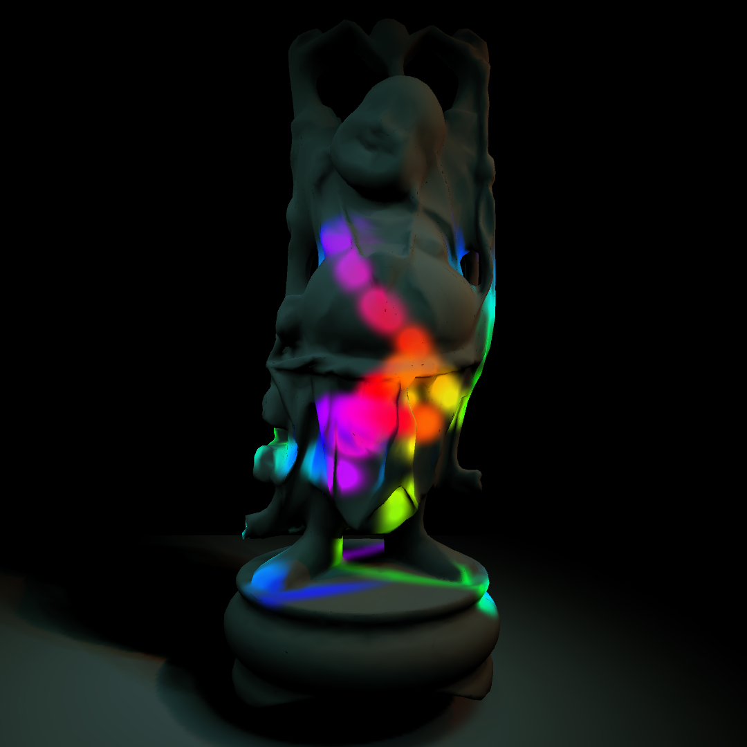
図4.14: 01_projectionSpray.unity
If you look at UnityCG.cginc, Lighting.cginc, etc., the built-in processing is written, and it will be a reference to implement various processing, so it is good to see it!